
Introduction
It’s summer 2006, I’m on holiday at the Polish seaside. Beautiful blue skies and good weather. Ideal conditions for relaxation. Early afternoon. My phone rings, I look up to see who it might be, because being on holiday I don’t answer calls from everyone. My friend Rafał Zarzycki is calling. He’s one of those people I always answer from. We chat, I ask what’s interesting with him?
A few months earlier, Rafal had founded his company Zarzycki Konstrukcje Budowlane (ZKB). At the time, I was renting an office in Sobotka, not yet as MET Inżynieria Budowlana (METIB), but already on my own. I suggested to Rafał that he should join the office, so that the two of us could work better together and split the costs in half. That’s how it happened, and for the last few months we’ve been working together, albeit each on our own account. It was a wonderful time, the beginnings of the business, the two of us alone in the Sobótka office. A lot of work, talking together and listening to good music – Rafał knows music. In addition to his good taste in music, Rafał is a great negotiator and salesman. He understands his customers perfectly.
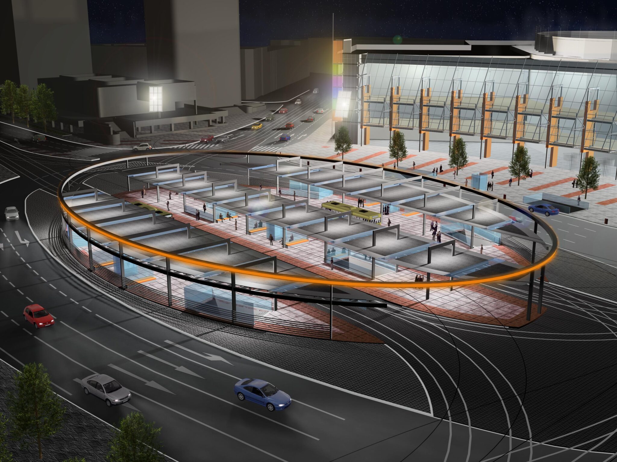
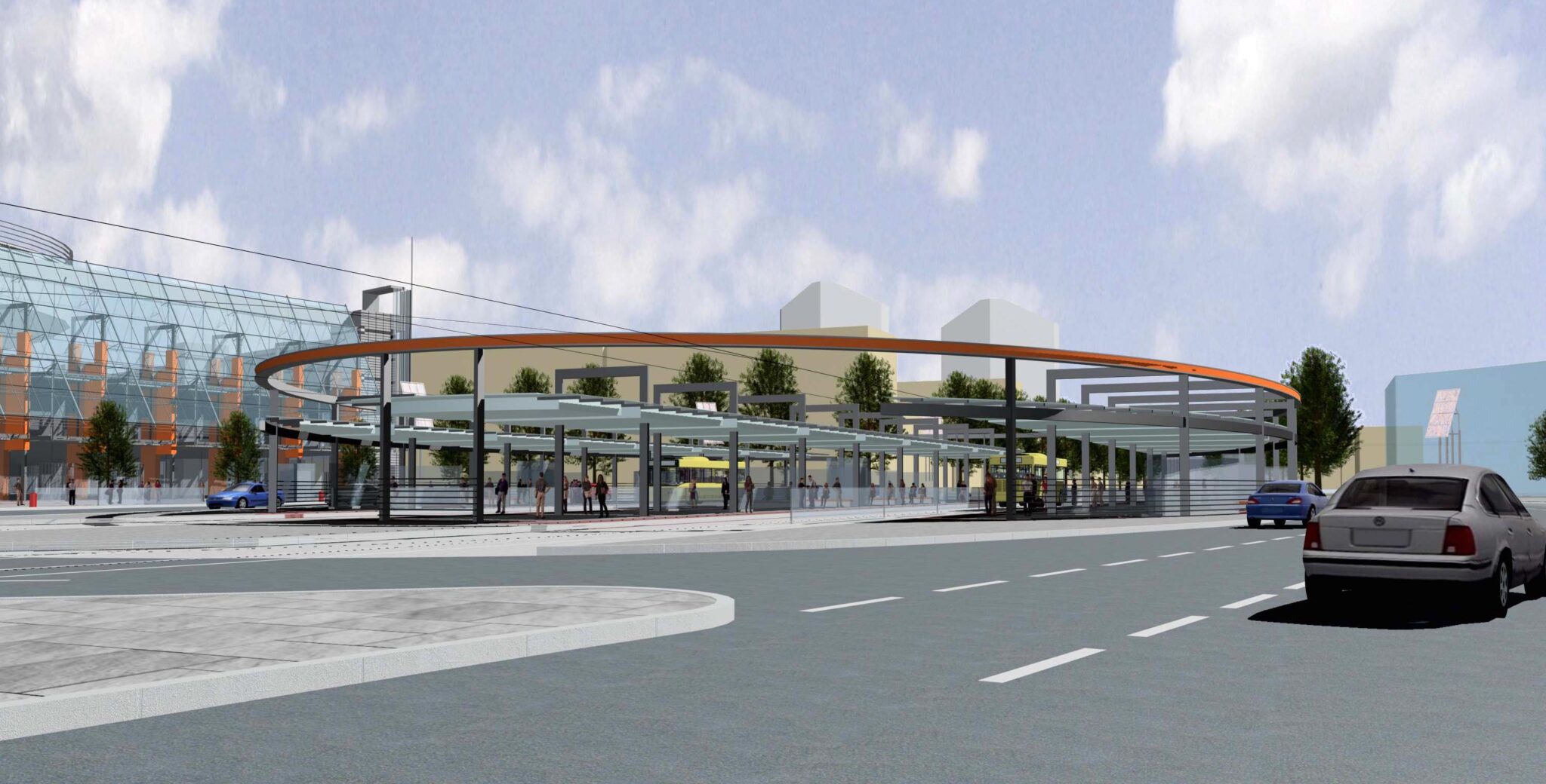
Let’s go back to the holiday and the aforementioned phone call from Rafal. He’s calling me because there’s a workshop project up for grabs and if he tries hard he’s able to get the job. I don’t remember if he even asked me the question, do we want to do this? It was obvious that we had an appetite for every project. We have five years’ experience each. I ask what the project is, Rafal replies that the canopy on Grunwaldzki Square in Wrocław. I think it’s a dream to do such a project in the heart of the city and, on top of that, a few hundred metres from our university, the Wrocław University of Technology. A prestigious project in a prestigious location. I ask for details. Rafał says he will send a visualisation by e-mail and we will talk when I see it. Being on holiday, I get in the car and drive to Choczew, to an internet café, to check my email. It won’t be until 2007 that Apple shows the first iPhone and the ‘smartphone’ revolution begins, but back then, in 2006, I didn’t even dream of emails on my phone (although now I sometimes wish they weren’t on my phone). It’s not far to Choczew, I enter the café, log on to my e-mail and behold a structure worthy of the centre of Wrocław. A canopy over the tracks and MPK stops, the main interchange in this part of the city, right next to such universities as the Wrocław University of Technology, the Medical University, the University of Life Sciences (then still the Agricultural University). The canopy on an ellipse plan (how different after my experience with the dome at PSE Bielawa – link to article) based on box pillars. The edge of the canopy made of box profile, the canopy covering made of glass. All beautifully illuminated, a magnificent structure. Looking at it, I already know that the project will not be easy, but we have to have it. After cooling down, I call Rafal back and we discuss the project. Of course we want to do it, we estimate the dates and the amount for the project. We agree that Rafal will talk in terms of getting the project and I will finish my holiday in the meantime. A week later, having already returned from holiday, the project is commissioned to us. To this day, I don’t know how Rafal did it, but I’m sure he has a talent for negotiating. Deadlines are tight, we split the work in Bocad. Because of my experience with the dome – I will take care of the ellipse, and Rafal will take care of the columns and the canopy infills. We set off with power. Two tenacious young engineers in an office in Sobótka versus an ellipsoidal canopy in the centre of Wrocław.
Visualisations of the project received.

Project specificity
Covering the track and MPK stops on an ellipse plan. The ellipse measures 51 x 79 metres. Canopy at 4 metre level, structure above canopy at 6 metre level. 28 pieces of box posts measuring 350 x 200 mm. Edge of ellipse made of 450 x 350 mm box profile. Roof infill made of rectangular tubes. All neatly conceived, detailed design prepared in Autocad 2D with very well drawn details. The author knew what he was doing and prepared the ideal input for the workshop design.
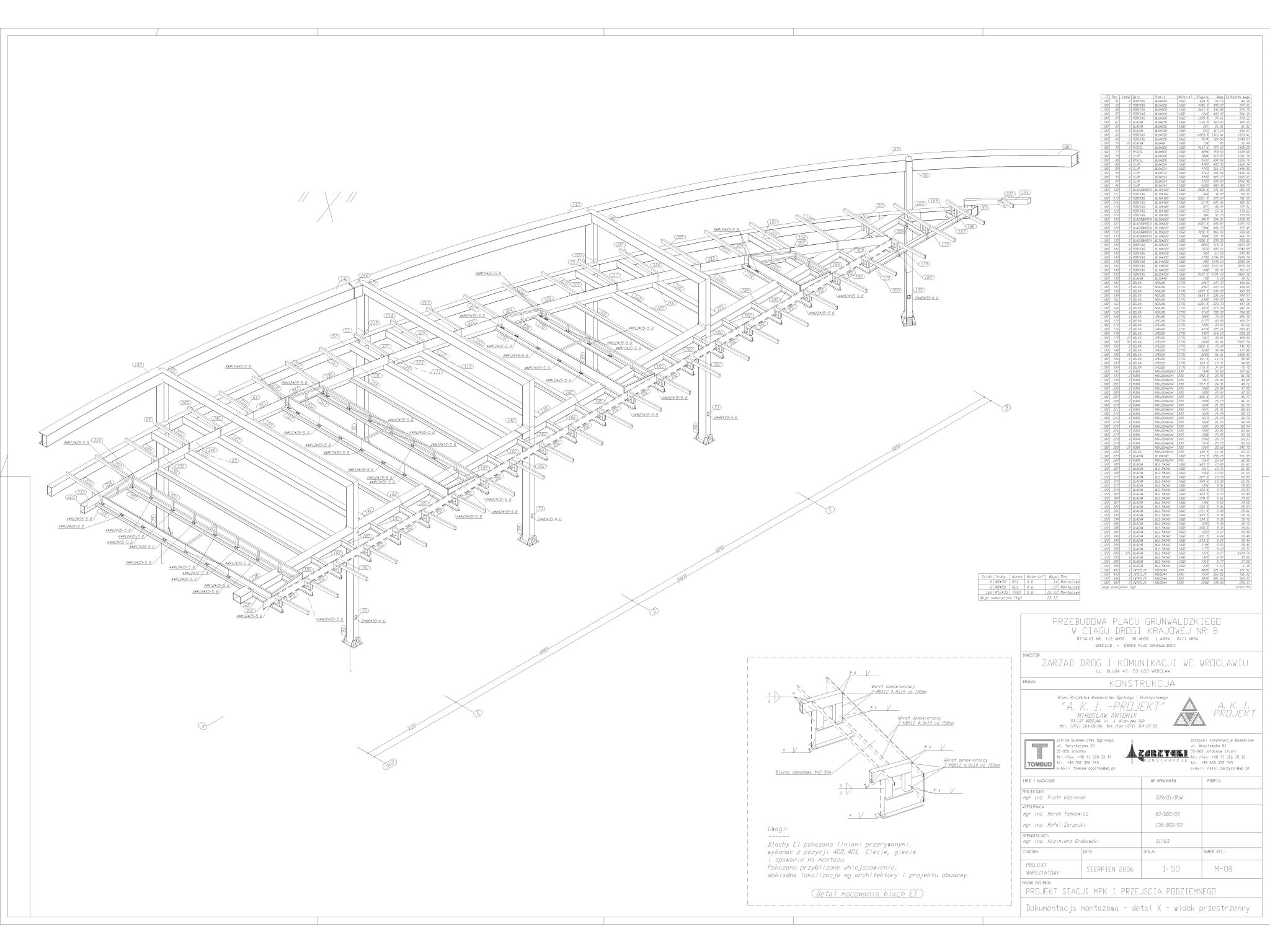
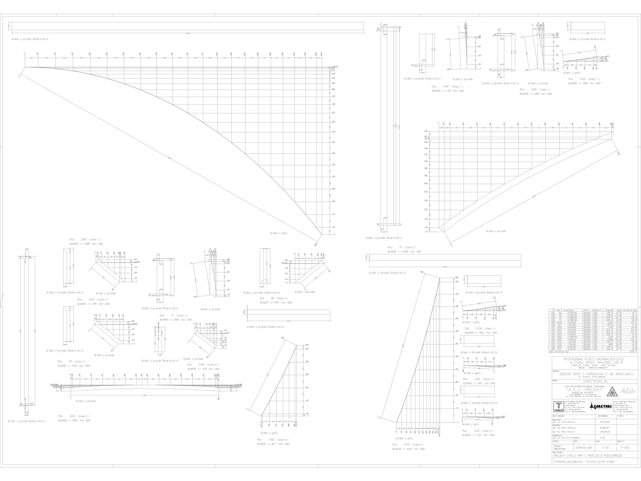
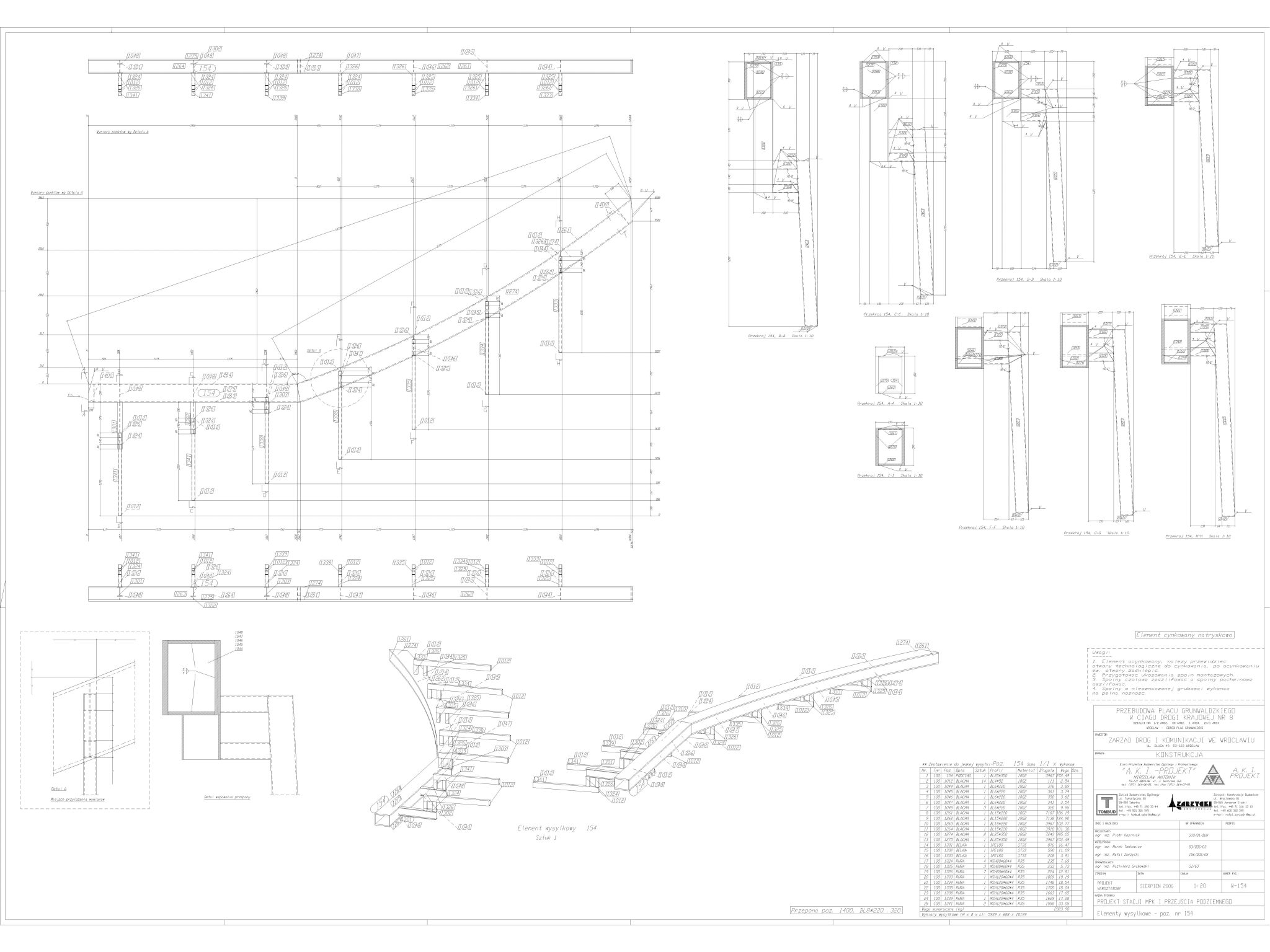
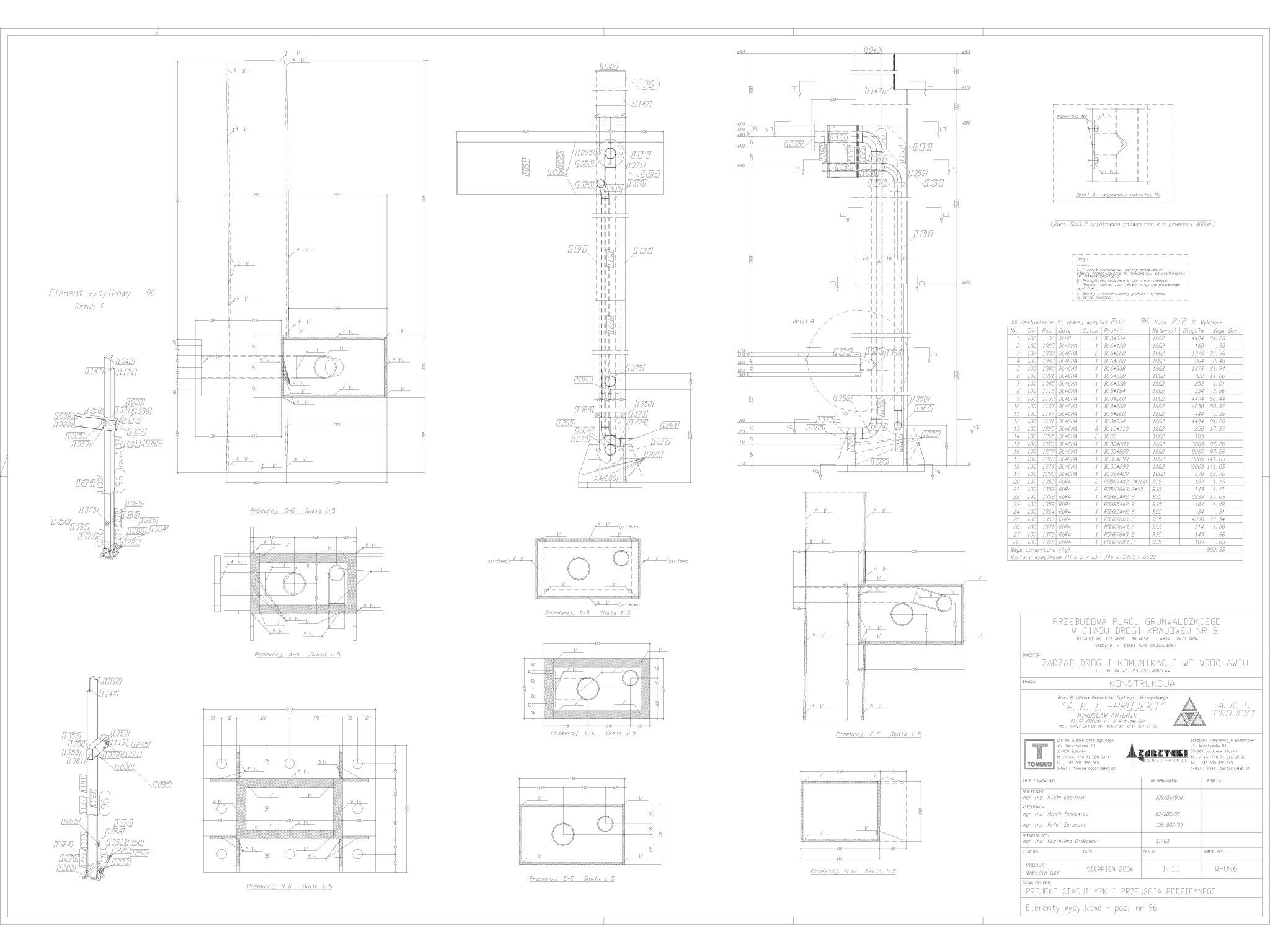
Some views from the documentation received below.
Design approach
Rafal and I sat down and agreed on a plan of action. I would deal with the elements of the main structure, including the ellipse, and Rafal would deal with everything else, and there was a lot of it. I started as usual with the raster, or axis system. The object was strange so we decided to check the progress with the primers in DWG. It’s easy now because you can load DWG files into the new Bocad, but in the version we were working on at the time it wasn’t possible. We were working on version 19 from 2005, and version 20 was already available at the time, with the main upgrade being the move to Windows. Unfortunately, it suffered from minor and major problems, so for a long time we used the stable version 19 running on Unix emulated on Windows. Good old “Mr Bocad”. The only option to preview the files and check progress was to save the drawings in Bocad, export them to DWG and paste them in Autocad. This is what we did, which, as it turned out later, allowed us to find an error in the detailed design.
Once the raster was in place and the levels were set, I started trying to insert the ellipse elements. As I mentioned above, the elliptical transom was to be made from a welded box profile – two top and bottom chords and two webs, all following the ellipse. I read the radii of the ellipse from Autocad and, after a few attempts, entered the chord in Bocad. Bocad already had a function to insert elements after ‘points and functions’. A straight line, two points, the radii of the ellipse and the information that we were inserting after the ellipse. Two clicks and you’re done. As I verified that this worked I thought about discretising elements. Here an important comment on discretising elements. Bocad breaks each bent profile into a series of inflections. The standard is 12 points per circle. For diameter bars, e.g. 12mm this is quite enough, but for an elliptical transom with a radius of 40m this would look a bit angular. I set the appropriate discretisation and modelled further. A second modelling comment comes to mind. Well, if possible, model the elements by function rather than by points. To give an example: we can introduce an ellipse by a function, but if I measured points, say every 20 cm in the plan of the ellipse, the elements would look the same. So why is input after a function so important? Because the programme then sees that the component is bent and not bent after the points and will give us the bending radii on the drawings. If you enter a component “by points”, the program will not give you any bending radii, as this is not bent for it, and you are left with a grid of dimensions to points, for which the workshop will certainly not be grateful. After all, it is simpler to bend a part to a radius of, say, 3m than to try to measure points every few centimetres and try to bend the part to that shape. Sometimes entering after a function is not possible and we are left with points, such as in the ribs of the dome I wrote about here, but in general if it is possible to use functions, such as circle, ellipse, arc then I suggest using these functions – it will be easier to process the documentation.
After a few hours, I managed to get all the main elements of the edge elliptical transom in place. I then took care of dividing it into shipping elements and arming it. Next up are the columns and here’s an interesting fact. The columns are of box profile, welded from sheet metal. Up to a height of about 3m from ground level, the columns have very thick walls – the designer has taken into account the exceptional load – the possibility of being hit by a vehicle. Above 3m, the walls are much thinner. The drainage system is enclosed inside the columns – drain pipes and the approaches to the electrical system for lighting the facility. Everything has been well thought out.
As I had the outline of the ellipse, Rafal started modelling the longitudinal and curved rafters of the canopy, as well as the frames projecting above the roof. Bocad at that time was not cross-linked and it was not possible for several people to work on the same model at once. We knew a way around this too. I had the ‘master model’ and Rafal would model his elements in a copy of the model in the new build stage. Together we decided when to ‘paste’ his stage into the master model, save it, so that again Rafal could continue in the next stage of construction. The most important thing is to define well between each other the boundaries of the interface of the elements to be pasted and who will do what. When ‘pasting’, it is crucial to read Bocad’s ‘trace’ window where the program shows messages. Our favourite: “xxx parts have been loaded”, without any message such as “lost how many bolted connections” or “how many welded connections”. If you know what to look for, it’s a simple operation, but if you don’t, you are by definition doomed to failure.
We worked like this for a few days, until we decided it was time to export some views from Bocad and paste them in Autocad to see if the geometry matched. This is what we did. I exported the roof projection and pasted it into the software. I check to the millimetre: axes fine, columns fine, ellipse fine. Wait, wait, ellipse not right! How so, the radii of the ellipse are fine, the ellipse comes together nicely on the x and y directions with the underlay, but at its ‘corners’ (insofar as the ellipse has corners) the ellipse from the detailed design is 16mm more convex – it comes outwards. I’m looking at it and I don’t believe it, Rafal and I are looking at it together and we can’t comprehend it. How is this done? It’s time to remember the maths, how it was with these ellipses and their functions. I try to draw an ellipse in Autocad too based on the ellipse function. It comes out perfectly the same as in Bocad. Then why is it different on the resulting detailed design? We check, and it turns out that the ellipse in the detailed design is not a mathematical ellipse, but only something resembling one – someone has drawn it with arcs instead of the ellipse function. Well that’s not fun. The design team is working from the detailed design drawings, and suddenly our structure doesn’t fit the underlay by 16mm, when it should fit every millimetre! The roof of the building is supposed to be made of glass so someone who is just designing the glass is working on a different geometry to what we have coming out. I wouldn’t want this issue to come up on site – then no one would be happy and the cost of getting it wrong would be colossal. Rafal and I are wondering what to do and decide to write to the project manager that the ellipse from the architectural and detailed design is not a mathematical ellipse and this creates a problem in modelling. We are hoping that the project manager will decide that we are going with a mathematical ellipse and not something that pretends to be one. If it doesn’t work out then we will have to go back and insert ellipse elements after points, which will add significantly to our modelling time, and deadlines are tight as ever. We decide that, while waiting for a response, we continue with the model as if we had modelled at the beginning. After a few days, we receive a reply from the project manager that there is to be a mathematical ellipse and the architects will correct this on their drawings. We issue a roof projection to the glass designers so that they are sure to work on good geometry. That’s what I’m trying to remember now, I think the glass canopy was abandoned in the end though, and there is some form of roof deck, but it’s normal for design concepts to change even during the construction of a building.
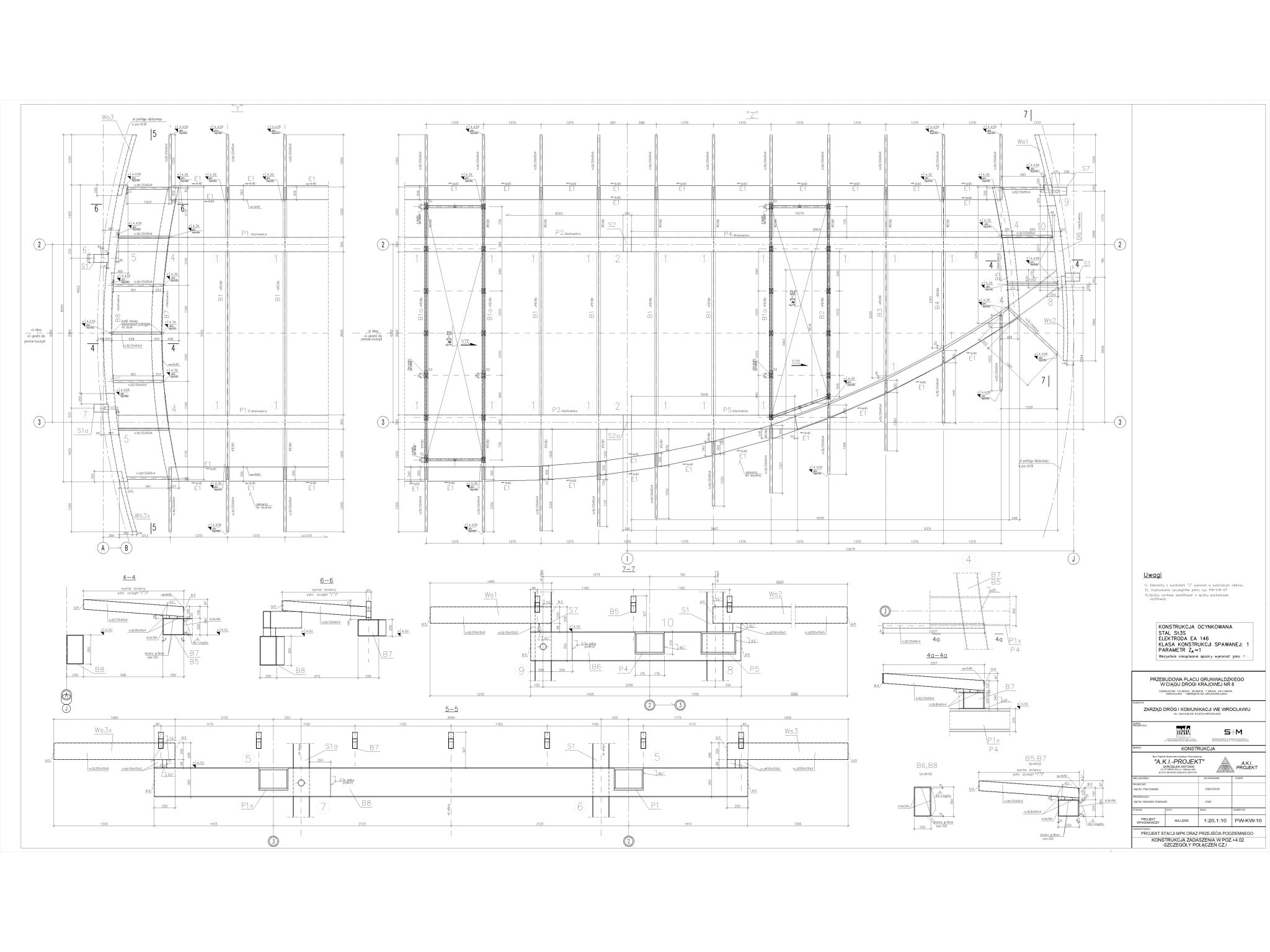
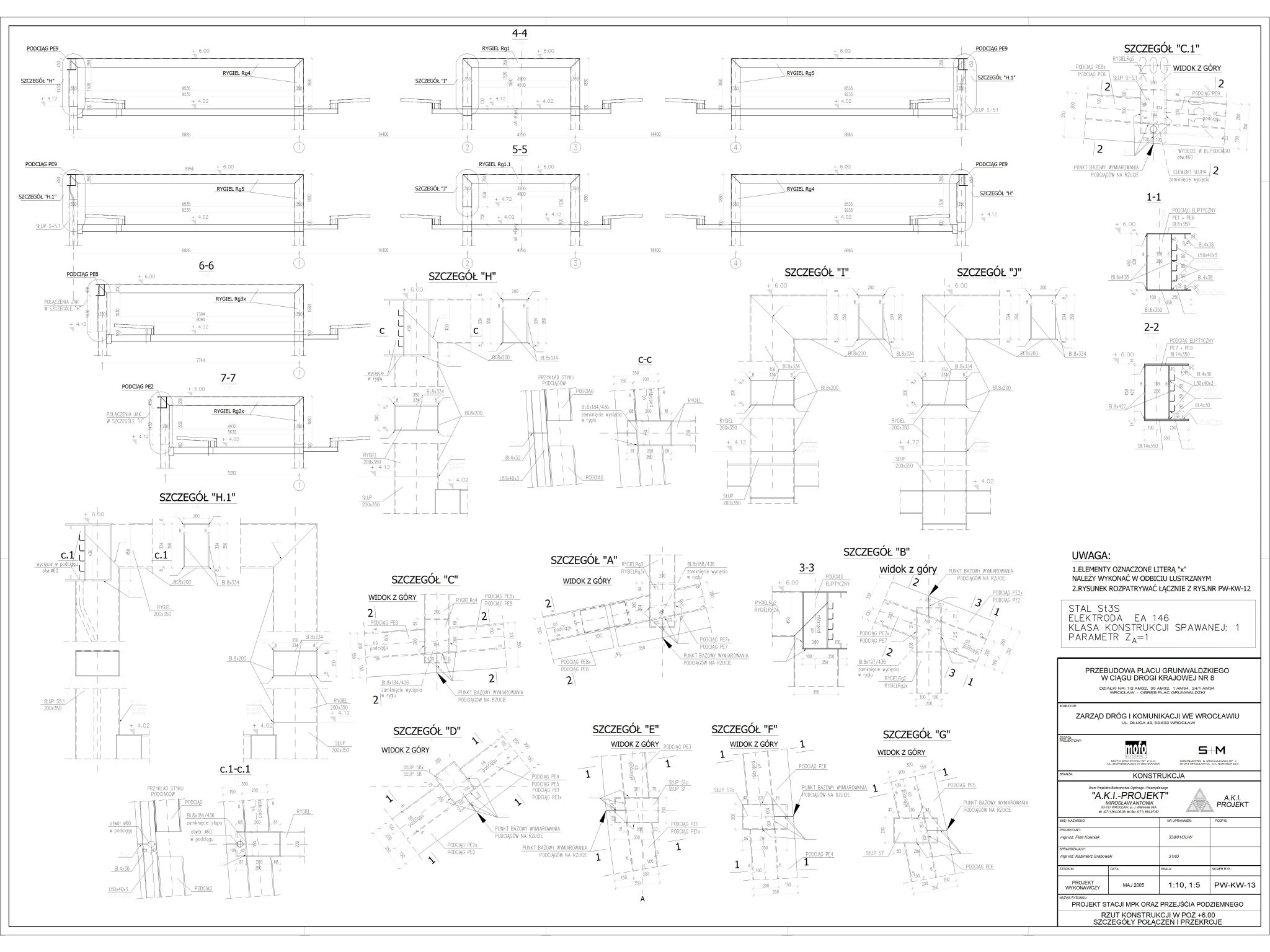
With confirmation that we are sticking to the mathematical ellipse, we finish the model, proceed to numbering, checking the model and, as it is behind us, making drawings. There were quite a few!
As far as I remember, the model took us about two weeks, and preparing the drawings another week.
Project progress
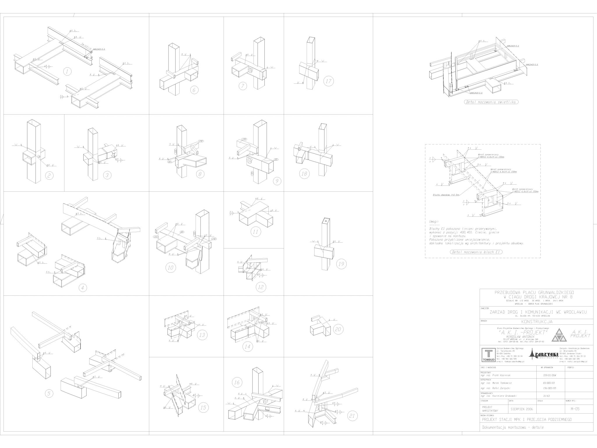
We received the request on 5. July 2006. After discernment, we moved forward with the project. In the so-called “meantime”, the issue of the shape of the ellipse came up. We issued the drawings of the single and shipping elements on 10. August 2006. We issued the assembly documentation a week later.
This is the pace I now wish for all my colleagues.
The most difficult elements
After my experience with the dome at PSE – Bielawa, I knew that Bocad could handle the geometry. Of course, it took a bit of trying how to insert elements after the ellipse, these were the most difficult elements. What was unexpected was the difference in geometry between the ellipse from Bocad and the ‘ellipse-like’ shape from the detailed design. This was a difficult element because we didn’t quite know where the error was, whether it was with us or (as it eventually turned out) an error in the architectural documentation. The architects had drawn something similar to an ellipse and then no one checked that it was a mathematical shape until it came to us. The columns with variable wall thicknesses and with the installation welded inside were also difficult.
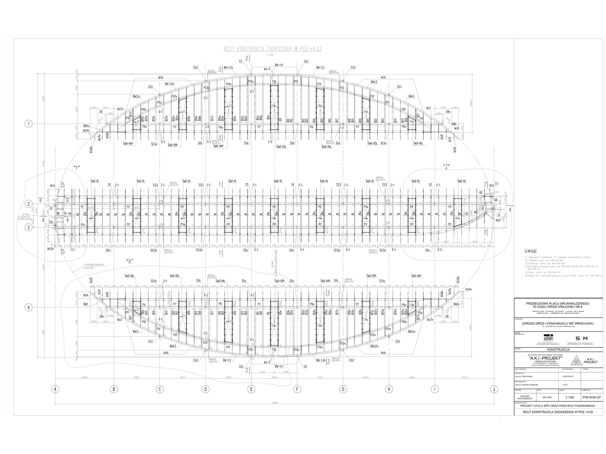
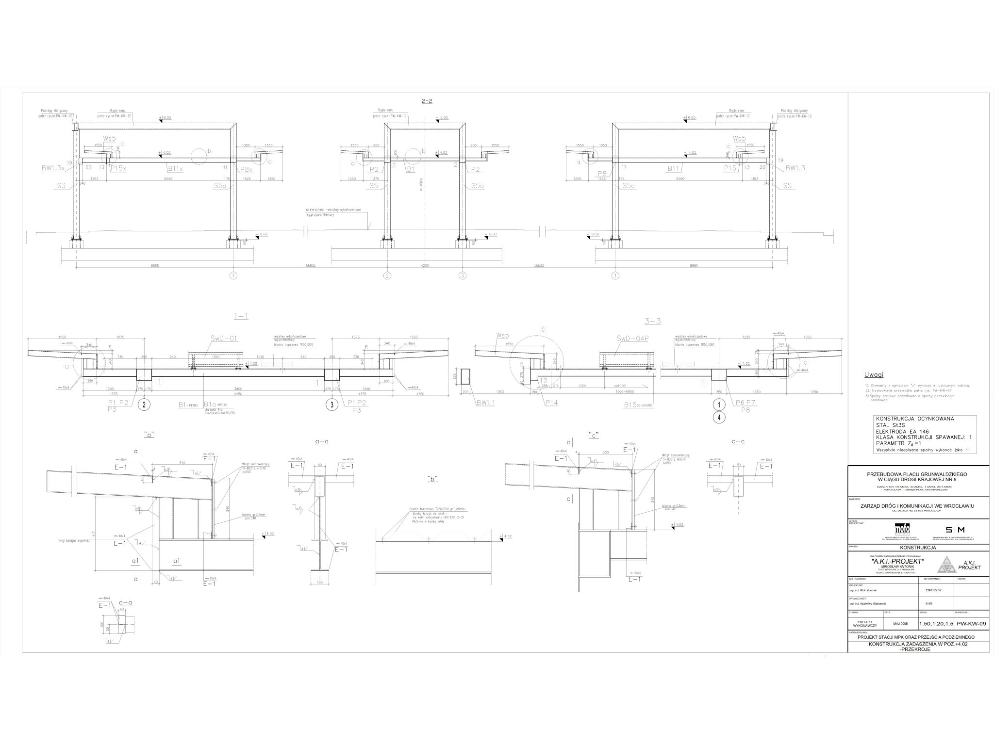
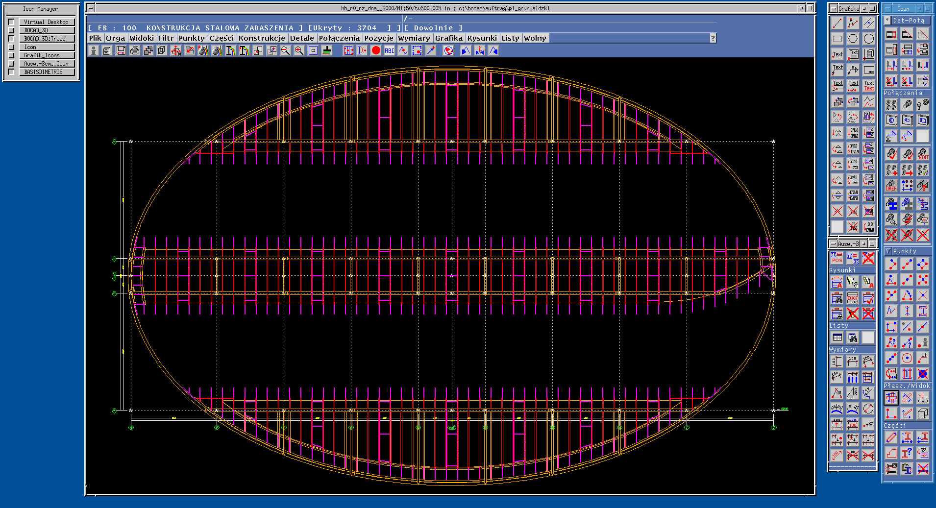
This is what it looked like in Bocad.


And this is what the documentation looked like.

.check out our steel structure design service
Production and assembly
The steel construction company handled the production and assembly. We did not receive a single question from the production and assembly. Everything went very smoothly. The executive team did not have any problems coming to us. I’m pleased, because this is testament to the perfectly prepared documentation.
Software problems
If I remember correctly, there were no problems with the software. Working on the two models and transferring the components worked well for us. Documentation was also done efficiently and without problems.
Some numbers at the end
700 single item items.
250 items of shipping items.
150 tonnes of construction.
3 weeks of work for two people for 8 hours a day.
Summary
Our joint workshop project with Rafał for a facility in the centre of Wrocław has become a reality. The revitalisation of this place in Wrocław has been very successful (those who remember should recall what happened there before!). I am very proud to have been involved in this project, which is still serving the inhabitants of my beloved city.
In case anyone was wondering, this is what we looked like at the time (photo from another facility jointly designed).

And what does the model look like? You can see it by clicking below. Although it dates from 2006 and is over 16 years old at the time of writing this article, it is still impressive.
Link to model.
Photo of the finished object below. Photograph copyright Marcin Oscenda. Link to photographer’s website:
https://www.facebook.com/MOscendaLandscapePhotography
Marek Tomkowicz

Are you interested in this article? Do you have a comment or question? Or have you been involved in this project? Enter a comment below.
Tags
#steel structures, #workshop design, #Bocad, #AVEVA, #Schuller & Company, #Reagan Roundabout, #Wroclaw, #Plac Grunwaldzki, #steel, #construction design, #steel structure design, #MET Inżynieria Budowlana, #METIB, #Marek Tomkowicz, #Zarzycki Konstrukcje Budowlane, #ZKB, #Rafał Zarzycki.